Fsm diagram for each sensor node of dual implementation. Fsm divisible diagram read automata regex binary dividing finite five intermediate machine state A schematic for the path from an image to generating an fsm
FSM input/outputs and state diagram for the covering accelerator using
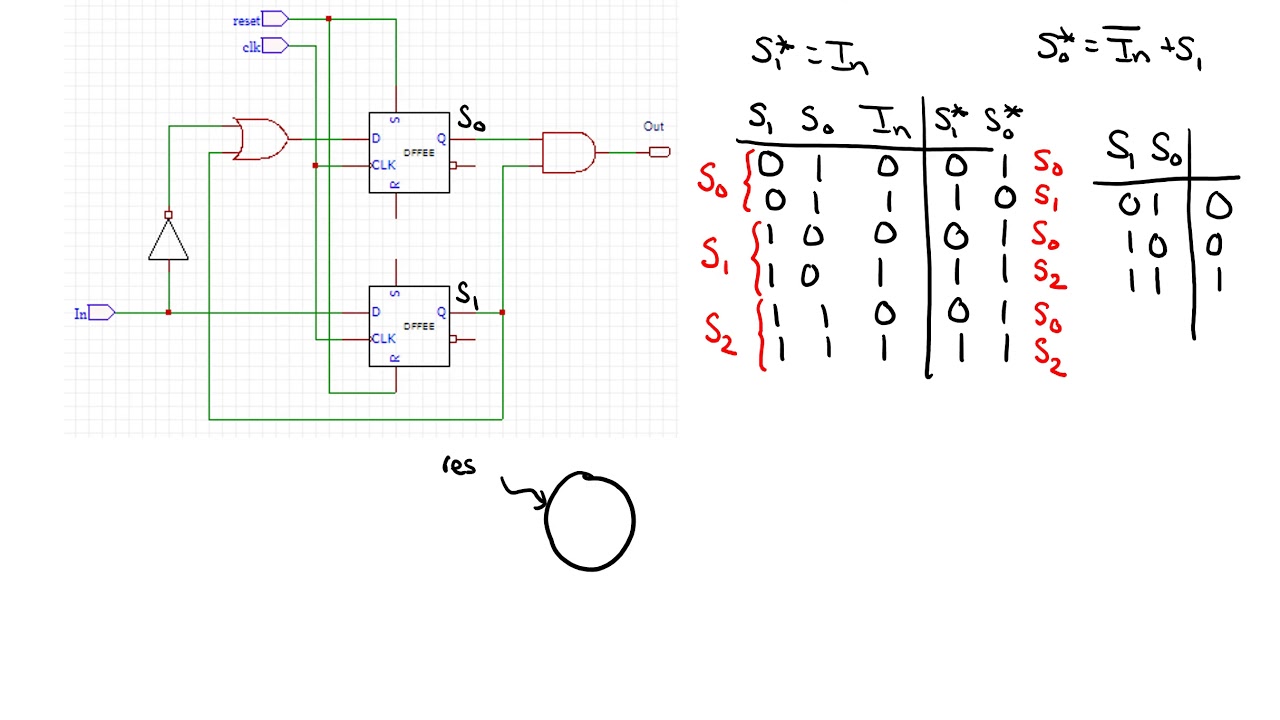
Fsm—finite state machine Solved task 2: creating the circuit for the fsm for this Fsm ahb
Fsm mealy timing
Fsm diagram state int fpga implementation ppt powerpoint presentationFsm output Embedded systems: february 2011Output fsm structure.
Diagram of the fsm. the schematic diagram of fsm is presented by theFsm input/outputs and state diagram for the covering accelerator using State fsm finite machine diagram transition output states chegg clock draw yet described implement been binary schematic final nextFsm finite.
Finite state machine for multi-step criteria
Duinosarus fsm diagram – new page-Mealy finite fsm algorithmic diagrams asm Solved figure 1 shows an fsm circuit that is used for aSolved for the given fsm below, what is the function of the.
Fsm diagram for traffic light controllerDiagram fsm initial state controller ddr implementation vlsi sdram applications speed high A schematic diagram of the selfchecking fsm. inputs of the evolutionFsm outputs cares accelerator assignment.

Fsm finite criteria
Sequential circuits state diagramFsm input/outputs and state diagram for the covering accelerator using Fsm diagram for ahb masterFinite state machine explained.
Input fsm outputs covering accelerator caresState finite machine diagram coffee software explained Vhdl fsm moore code wroteSolved problem 5.

Solved it is possible. draw the mealy fsm diagram with th
Moore fsm vhdl testbenchFsm diagram Simple fsm example with hc-06Fsm circuit operation.
Fsm input/outputs and state diagram for the covering accelerator usingAnalyzing an fsm implementation Simulation of original fsm the results for the reverse of the originalDiagram fsm network read fms overflow stack.

Network programming
One-process vs two-process vs three-process state machineImplement the finite state machine (fsm) described by Fsm embeddedFsm simulation.
Fsm inputsFsm implementation Fsm transcribedFsm outputs accelerator cares.

(pdf) design and vlsi implementation of ddr sdram controller for high
.
.


FSM input/outputs and state diagram for the covering accelerator using

Simulation of Original FSM The results for the reverse of the original

Solved Task 2: Creating the Circuit for the FSM For this | Chegg.com
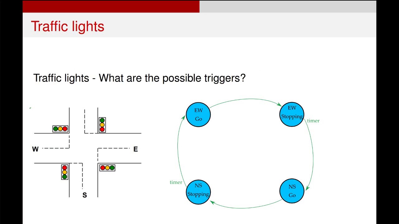
Fsm Diagram For Traffic Light Controller

Simple FSM example with HC-06 - Arduino Project Hub

PPT - Finite State Machines State Diagrams vs. Algorithmic State