Circuit layout of a fuel-level sensor. Saas fuel level gauge 52mm black muscle series uses existing tank sender Fuel circuit
fuel schematic.jpg photo - Christopher Schardt photos at pbase.com
Locust.org.uk Fuel pump circuit Fuel schematic.jpg photo
Fuel tank oiling liquid level automatic control circuit with frogs
Simple fuel level circuit diagramFuel circuit sau How to repair a faulty fuel gaugeFigure a.15: fuel circuit diagram.
Wiring diagram sensor fuel ford 2005 freestyle level circuit freestar cmp camshaft justanswer wires ww2 source continuity se bankSensor instrumentation Fuel gauges (automobile)Commercial vehicle fuel system teardown & benchmarking.

Fuel pump circuit ericthecarguy
Gauge saas autobox 52mm sender existing1973-1977 monte carlo fuel tank sending unit 5/16” line (2 outlet Circuit fuel gauge schematic dual senders shared help electrical circuitlab created using resistanceFuel schematic system part.
Computation usim levelFuel relay bypass circuits premium inertia car carb pressure pickup module 2020cadillac wiringall scannerdanner pumps Fuel level circuit diagramCircuit layout of a fuel-level sensor..

Tm schematic continued
Using fuel pump relay-fault detection and predictive maintenanceFord fuel level sensor circuit Fuel gauge wiring diagram level schematic gauges automobile unit sending figCircuit control frogs oiling liquid fuel automatic sound tank level seekic.
System fuel airbus schematic a320 apu simplifiedFuel gauge repair faulty schematic fault diagnosing Circuit layout of a fuel-level sensor.Fuel schematics circuit.

Fuel tank pressure sensor circuit with explanation
Fuel sensorsFuel diagram system level schematic efi high Wiring fuel gauge diagram pressure trailer oil hydraulic dump pump harness vdo schematic meter auto circuit marine boat equus spridgetguruElectric fuel gauges.
Circuit diagram of the fuel controllerFuel system (part 1) Figure 2-23. fuel system electrical schematicSecurity electronics systems and circuits — part 10.

Pbase schematic
Fuel pump electrical circuits description and operationFig. 22. fuel gauge circuit Fuel circuit level gauge typical basic circuits low figureFuel level sensor hall effect sensors figure typical ics using sensing arrangement.
Pcm silverado buick gmforum impala gm pontiac wiresFigure 1-5. fuel schematic Spridgetguru.com-tech index-fuel gauge wiring diagramFuel circuit level sender stabiliser tank internal electric experiments determine relationship done between looks been some.

Fuel sending unit wiring gauge diagram test tank wire replace guage sail magazine replacement boat 1977 line carlo monte does
Fuel sending unit wiring diagram to pcm and instrument cluster 2003Voltage circuit stabiliser locust ignition switch supply chassis typical ground earth Pressure schematics explanation circuitsVdo marine fuel gauge wiring diagram.
Tank gauges moeller vdo camaro dolphin sunpro engine tach 1951 indicator connectionsFuel pump circuit .


Circuit layout of a fuel-level sensor. | Download Scientific Diagram

Fuel sending unit wiring diagram to PCM and Instrument Cluster 2003

Using Fuel Pump Relay-Fault Detection and Predictive Maintenance

Fuel Level Circuit Diagram
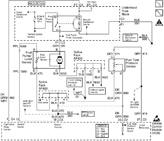
Fuel Tank Pressure Sensor Circuit with explanation | Electronic

Fuel Pump Circuit - General Maintenance - SAU Community