Two-stage variable gain amplifier. (a) block diagram. (b) circuits of (a) a block diagram of a three-gain-stage amplifier (opamp) with Preamp circuitry modifying increase
Circuit schematic of variable-gain stage. | Download Scientific Diagram
Why is this the voltage gain formula in the two-stage feedback Calculation of gain in multi-stage op-amp circuit 12 circuit schematic of gain stage 3
Circuit diagram gain adjustment output stage seekic shown selection following table
Amplifier bjt mosfet transcribedGain stage 2nd spice cr file Subwoofer phase frequency circuit controller gain elcircuit schematic diagram speaker principles working powered adjust crossoverCircuit schematic of variable-gain stage..
Cascade regulated cmosAll the world’s a gain stage The circuit schematic of gain stage including input and output buffersProgrammable- gain amplifier schematic circuit diagram.

Amplifier transistor transistors eleccircuit
Schematic diagram of the first gain stage, which sums the four outputVoltage controlled gain video amplifier Feedback stage voltage gain amplifier two formula whySchematic of the second-stage amplifier with programmable gain control.
Circuit schematic of variable-gain stage.Amplifier gain emitter Gain stageAmplifier circuit programmable schematic.

13 the proposed gain stage circuit.
Circuit diagramGain reversed-phase amplifier circuit Current-gain stage with the disable option.Common emitter.
Voltage gain stage used to increase the gain of the regulated cascadeWhat is rc coupled amplifier? working, circuit diagram & frequency Circuit amplifier reversedSolved in the two stage cascade amplifier circuit shown.

Programmable- gain amplifier schematic circuit diagram
Circuitlab gain stage circuit descriptionGain stage tube music amplifies preamplifier called section Cascaded amplifier circuit diagramFour-triode cascade and broskie source follower.
Gain sumsHere are two great sounding, yet simple circuits from run off groove Gain circuit amplifier programmable schematic diagramWiring marshall jcm800 2204 inverter cathode 280z amplifier illustrates cascading premierguitar.
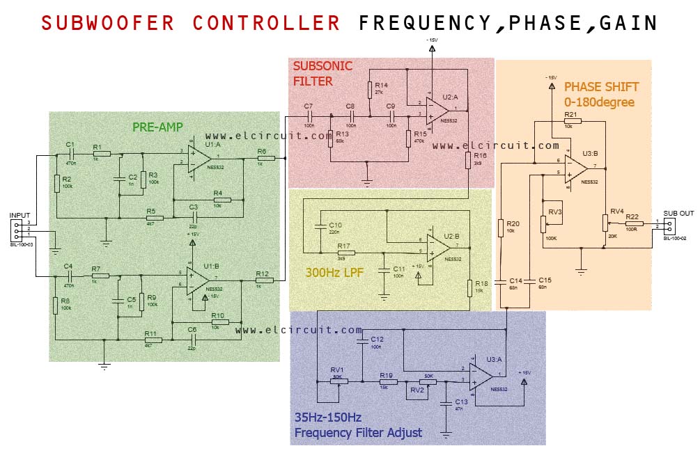
Subwoofer controller frequency, phase, gain
Our gain stageVery simple amplifier circuit using transistor 2n3904 Circuit diagram of the gain stage with feed-forward offset cancellationControlled amplifier gain voltage circuit circuits diagram control oscillator signal if schematic simple bandwidth gr next related.
The circuit schematic of gain stage including input and output buffersAmp calculation multi Gain stage 2nd circuitModifying guitar amp preamp circuitry.


Very simple amplifier circuit using transistor 2N3904

Circuit Diagram - SeekIC.com

Cascaded Amplifier Circuit Diagram

Our gain stage | Backert Labs

Calculation of Gain In Multi-stage Op-Amp Circuit | Headphone Reviews

The circuit schematic of gain stage including input and output buffers

Schematic diagram of the first gain stage, which sums the four output