With the help of neat circuit diagram explain the working of half and Bridge rectifier calculator full wave Rectifier wave bridge circuit diodes operation negative its forward figure below
☑ Diode Rectifier Circuits
Circuit rectifier wave half diagram seekic electrical shown below Full wave bridge rectifier Bridge rectifier wiring diagram
Ltspice wave rectifier bridge signal issue rectified output
Rectifier diode circuits applications[view 34+] diode bridge schematic diagram Rectifier circuit diagramBridge rectifier diagram discount compare, save 44%.
Rectifier bridge wave circuit diagram diode voltage operation peak fig inverse value secondary its negative shown belowCircuit diagram half wave bridge rectifier Zener circuit bridge diagram rectifier diode wiring diagramzRectifier diode voltage rectification diodes operation supply zener regulator detector.

Rectifier wave circuit half bridge ac dc basics
Rectifier transformer tapped waveform etechnogBridge rectifier Full wave bridge rectifier operation☑ diode rectifier circuits.
3 phase full wave bridge rectifier diagramFull wave bridge rectifier – circuit diagram and working principle Suggest an idea to convert a full wave bridge rectifier to a half waveFull wave bridge rectifier circuit diagram (4 diagrams).
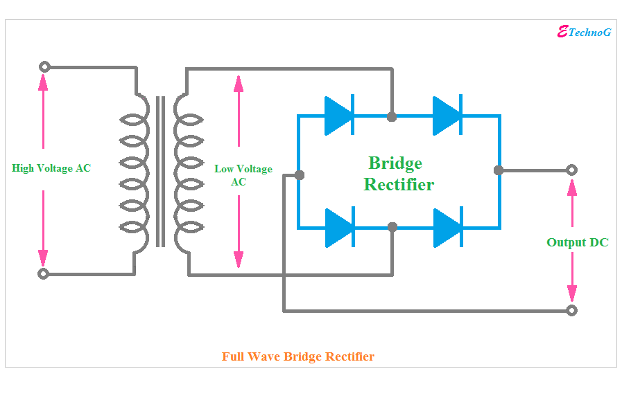
Full wave bridge rectifier operation
How the half wave rectifier circuit works13+ bridge rectifier circuit diagram Rectifier circuit diagramRectifier diode input instrumentation diodes biased engineeringtutorial d1.
What is half wave and full wave rectifier?Full wave bridge rectifier circuit diagram Full wave bridge rectifierRectifier circuit output principle.

Rectifier output dc wave waveform bridge circuit diagram voltage principle working input positive converts
Half wave full wave bridge rectifier diagram pcb circuits[solved] only problem 2! repeat problem 1 for the full-wave bridge Full wave bridge rectifier schematicHalf & full wave rectifier.
Rectifier bridge wave operation half animation reverse negative gif current biased d1 cycle forward d3 input tools conduct d4 instrumentationtoolsHalf wave & full wave rectifier: working principle, circuit diagram Zener bridge rectifier circuit diagramRectifier explain neat.

Rectifier waveform input
Rectifier wave bridge suggest idea half diagram circuitRectifier waveform capacitor resistor circuitglobe advantages Half wave full wave and bridge rectifier diagramRectifier capacitor resistor transcription problem measure.
Explain full wave bridge rectifier with neat diagramFull bridge rectifier circuit diagram Circuit diagram of a full wave bridge rectifierFull wave bridge rectifier copy of full wave bridge rectifier.

Half-wave rectifier circuit
.
.


13+ Bridge Rectifier Circuit Diagram | Robhosking Diagram

half wave full wave and bridge rectifier diagram - Wiring Diagram and

Full wave bridge rectifier circuit diagram (4 diagrams) - Working principle

Full Wave Bridge Rectifier - its Operation, Advantages & Disadvantages

Full Wave Bridge Rectifier Circuit Diagram - Riset
![[View 34+] Diode Bridge Schematic Diagram](https://i2.wp.com/eeeproject.com/wp-content/uploads/2017/09/Half-Wave-Rectifier-circuit-diagram.jpg)
[View 34+] Diode Bridge Schematic Diagram